Industries


Information Models and UML – A Short Tutorial 


Information models are used commonly to capture the flow of information between different components of a system. Instead of one view, these models present different views so that different types and levels of details can be understood by the analysts.
Over the years, a very large number of description and diagramming notations have been employed in the IS field. At the time of this writing, the most popular technique is based on object oriented concepts and Unified Modeling Language (UML).

UML has been adopted by the Object Management Group (OMG) as a standard modeling technique. The purpose of Object Management Group (www.omg.org) in adopting UML is to:

  • Promote theory and practice of object technology for development of distributed systems

  • Provide common architectural framework for object oriented

    UML provides a large number of diagrams for information modeling. However, the following three UML diagrams are used most frequently
     

  • Use case diagrams and use case descriptions – show user roles and how they use the system

  • Class diagram – definition of system components

  • Systems sequence diagrams (SSDs) – define inputs and outputs and sequence of interactions between user and system for a use case

    The following three examples show simplified versions of a use case, a class diagram and an SSD for order processing.


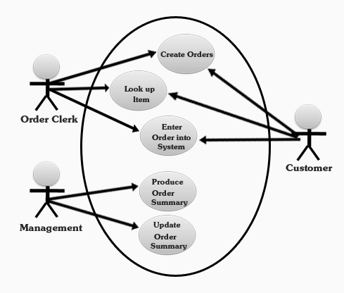
Example: Order Processing Use Case

This use case shows the main activities (circles) performed within an order processing system. It also shows how the three main users (customers, managers, an order clerk) interact with these activities. 

Example: Order Processing Class Diagram

This class diagram shows the main classes (objects) in the order processing system (i.e., Sales Marketing-Sales Department, Customer, Service Department). For each class, it shows the attributes (e.g., name, address) and the methods (operations) performed.

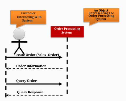
Example: Order Processing SSD   

This SSD (system sequence diagram) displays the sequence of interactions between the customer and the order processing system.  The arrows show the sequence (top to bottom). For example, create an order is the first interaction generated by the customer and query response is the last interaction generated by the order processing system.   

References:

§  OMG website (www.omg.org)
§
 
Roques, P., "UML in Practice: The Art of Modeling Software Systems", Wiley, 2004: